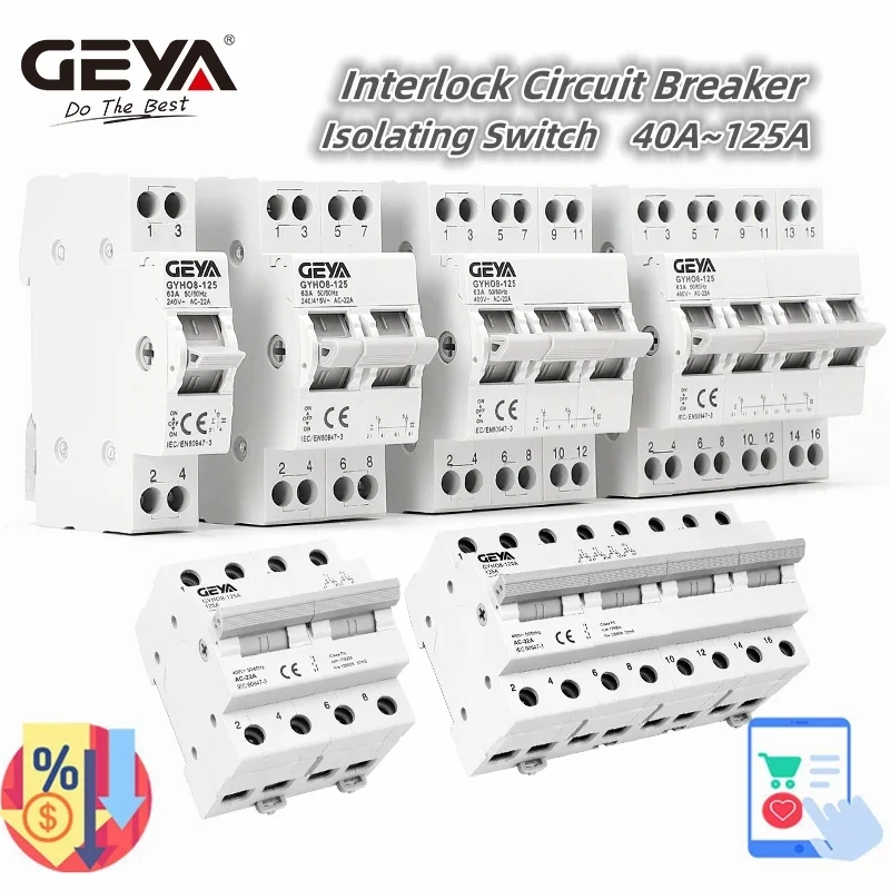
GEYA GYHO8 1P 2P 3P 4P 40A 63A 100A 125A Interlock Circuit Breaker AC Din Rail Manual Transfer Switch ATS
$2.97 – $105.18
Description
- Rated Voltage: 220/380V
- Type: Circuit breaker
- Is Smart Device: No
- is_customized: Yes
- Model Number: GYHO8 MTS
- Type: Mini
- Brand Name: GEYA
- Origin: Mainland China
- Certification: CE
- Product Name: Manual Transfer Isolating Switch
- Rated Current: 40A 63A 100A 125A
- Poles: 1P 2P 2P 3P 4P
- Rated Voltage Ue: AC220/240V, 400V
- Rated Frequency: 50/60Hz
- Standard: IEC/EN60947-3
- Mounting: Din Rail

General
GYHO8 dual power manual isolation switch has four functions-on, off, conversion and isolation. It can be freely switched on and off between two loads carried by a group of lines, or on two power sources.
It is used for on-off and switching , using DIN standard rail (35×7.5) installation.
The shell is made of PA66 injection molding, with high flame retardant performance.
It is an ideal product that needs to be used for switching and opening and closing in industrial equipment and circuits.
The rated current is 40A/63A/100A/125A, and it is convenient and safe to install and wire on the guide rail.
Instructions for use
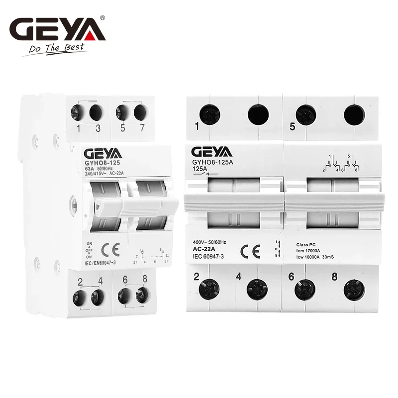
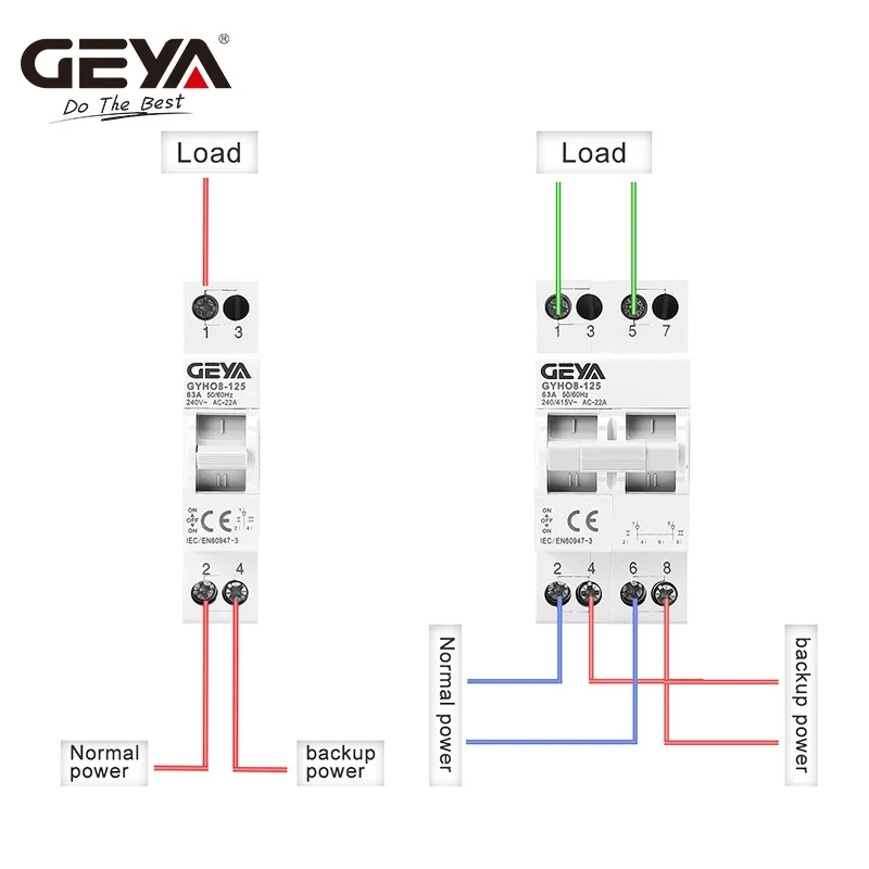
1P Manual Transfer Switch(MTS)
1.When the handle on the I position: 1 and 2 are connected
2.When the handle on the II position: 1 and 4 are connected
3.When the handle is in the middle position: both groups are disconnected.
2P Manual Transfer Switch(MTS)
1.When the handle on the I position:
1 and 2 are connected
5 and 6 are connected.
2.When the handle on the II position:
1 and 4 are connected
5 and 8 are connected.
3.When the handle is in the middle position: both groups are disconnected.
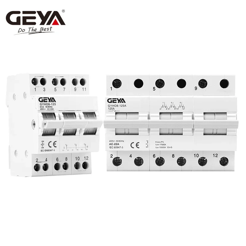
3P Manual Transfer Switch(MTS)
1.When the handle on the I position:
1 and 2 are connected
5 and 6 are connected.
9 and 10 are connected
2.When the handle on the II position:
1 and 4 are connected
5 and 8 are connected.
9 and 12 are connected
3.When the handle is in the middle position: both groups are disconnected.
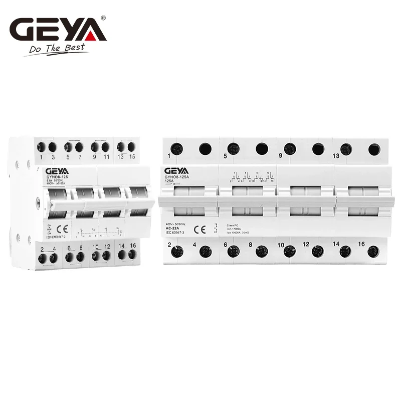
4P Manual Transfer Switch(MTS)
1.When the handle on the I position:
1 and 2 are connected
5 and 6 are connected
9 and 10 are connected
13 and 14 are connected.
2.When the handle on the II position:
1 and 4 are connected
5 and 8 are connected
9 and 12 are connected
13 and 16 are connected.
3.When the handle is in the middle position: both groups are disconnected.
The position of the incoming and outgoing wires can be adjusted according to actual needs (the upper and lower out are not necessarily required, when used for dual power switching, the lower in and upper out must be used.)



Reviews
There are no reviews yet.